Tag Archive: ws2812


Okay, now, let’s implement a WS2812-controller using an STM32F103 microcontroller using DMA transfers. Again, we have a HAL implementation and a direct implementation. Basically, I switched to the direct implementation because I couldn’t find something in the HAL implementation, but I found it later.

Memory considerations. The example from the HAL uses 32 bit values. As I only need low values, 8 bit values would be fine, and needed to minimise the memory usage. As I couldn’t find the option to use 8 bit values, I switched to a direct implementation.

Now… the option is there… but I was looking where it was set to 32. So, I was looking for something mentioning 32. However, it’s called
hdma_tim.Init.PeriphDataAlignment = DMA_PDATAALIGN_WORD ;
It didn’t occur to me to seach for WORD to represent uint32_t. Basically, to me, WORD is a system-specific thing. Different platforms have different word sizes, so using WORD to indicate a 32 bit int doesn’t come natural to me.

Nevertheless, I continued with my direct implementation. I suppose, this way I get to know the hardware, and I am doing some things I believe are not available in the HAL, or they’re hidden so well, that it’s easier to find them in the datasheet.

So, there is a DMA controller. Bascially, I point to to a block of memory and a peripheral. The peripheral requests the next unit of data when it’s ready to process it. That’s basically how it works.

The DMA controller has channels. One thing to be aware of, each peripheral is associated with a certain channel. You have to use the correct channel or it won’t work.

So, let’s have a look at this DMA controller. To use the DMA Controller with Timer 2, we need DMA Controller 1, Channel 2. We need to associate the DMAR register of the Timer to the DMA Channel. The timer peripheral uses 16 bit values. As we have low values and want to conserve memory, the data buffer is 8 bit.

	DMA1_Channel2->CPAR = &(TIM2->DMAR); // DMA 1 Channel 2 to TIM2

	DMA1_Channel2->CCR  = 0x00;
	DMA1_Channel2->CCR  |= 	(0x01 << DMA_CCR_PSIZE_Pos); // Peripheral size 16 bit
	DMA1_Channel2->CCR  |= 	(0x00 << DMA_CCR_MSIZE_Pos); // Memory size 8 bit
	DMA1_Channel2->CCR  |=  (0x1 << DMA_CCR_DIR_Pos);   // Memory to Peripheral
	DMA1_Channel2->CCR  |=  (0x1 << DMA_CCR_MINC_Pos);   // Memory increasement
	DMA1_Channel2->CCR  |=  (0x0 << DMA_CCR_PINC_Pos);   // Peripheral increasement
	DMA1_Channel2->CCR  |=  (0x0 << DMA_CCR_CIRC_Pos);   // Circular mode
	DMA1_Channel2->CCR |= DMA_CCR_TCIE; // Enable transfer complete interrupt

Now, let’s look at the timer. Here, we say where the data should go that is offered by a DMA tranfer. We set it to go to the CCR1 register. The compare register that sets the PWM period. Each timer has 4 channels, and 4 of those registers. Here, I set the timer to receive 4 transfers at a time. This way, I output to all 4 channels at the same time. Furthermore, I have to enable the Update DMA request.

	TIM2->DCR |= (( 12 ) << TIM_DCR_DBA_Pos); // DMA Transfer Base address CCR1
	TIM2->DCR |= (( 3 ) << TIM_DCR_DBL_Pos); // 4 Transfer at a time (CCR1 to CCR4)
	TIM2->DIER |= TIM_DIER_UDE; // Update DMA Request Enable

When this is set up, a DMA transfer can be initiated by

	DMA1_Channel2->CNDTR = size;
	DMA1_Channel2->CMAR = memory;

	TIM2->CCMR1 |= 1; // enable timer
	DMA1_Channel2->CCR |= 1; // Enable DMA

	TIM2->EGR = TIM_EGR_UG;

Point to the memory block, set the length of the block, enable timer, enable DMA, and finally, let the timer request an update from the DMA controller. Now, each period the timer will send an update request to the DMA controller, and this way, we can control four LED strips simultaneously. And this is what mentioned before, I couldn’t find an option in the HAL to control multiple channels simultaneously.

So, I’ve decided to create my own controller for WS2812-compatible (SK6812, PD9823) leds. These leds are referred to as “clockless”, as they only have a data line and no clock line. The data is transmitted in a serial protocol, which encodes a zero as a short high, long low, and a one as long high, short low. A short high pulse should be less then 440 ns, and a long high pulse should be at least 625 ns, to cover most of the variants. Using this protocol, the data is transmitted as RGB colour data, 8 bit per pixel, thus 24 bits per LED. The order is rather GRB, for SMD leds as found on LED strips, but RGB for trough hole leds (such as PD9823). The data is transmitted Most Significant Bit First. Each led on a led strip reads 24 bits and applies that colour, and forwards the remaining bits to the next led in the chain.

Looking at that protocol, I imagined it could be implemented using a PWM generator, continuously updating the PWM period. I’ve decided to implement this on an ST microcontroller, the STM32F102C8T6. I had one of these laying around. I’ve ordered such a microcontroller on eBay, over a year ago, and never gotten into doing something with it, until now. I will write another post about microcontrollers soon, but now, I am writing about my experiences controlling the ws2812-style leds. This will include some implementation details specific to the STM32F103 microcontroller.

The STM32F103 microcontroller has timer units which include a PWM mode. You set a period time, and a compare time less then the period time. This will generate a PWM signal with said period and compare time. My first naive implementation was to set the next period time in the interrupt handler when the compare time expired. My first attempt is based on the examples provided with the STM32Cube SDK. It uses the HAL provided by ST. Obviously, the first attempt didn’t work. It never does. (I wrote this months ago… there might be some details off)

void pwm_init() {

  TimHandle.Instance = TIM2;

  TimHandle.Init.Prescaler         = 9; 
  TimHandle.Init.Period            = 10;
  TimHandle.Init.ClockDivision     = 0;
  TimHandle.Init.CounterMode       = TIM_COUNTERMODE_UP;
  TimHandle.Init.RepetitionCounter = 0;

  if (HAL_TIM_PWM_Init(&TimHandle) != HAL_OK) {
  /* Initialization Error */
  Error_Handler();
  }

  /*##-2- Configure the PWM channels #########################################*/
  /* Common configuration for all channels */
  sConfig.OCMode       = TIM_OCMODE_PWM1;
  sConfig.OCPolarity   = TIM_OCPOLARITY_HIGH;
  sConfig.OCFastMode   = TIM_OCFAST_DISABLE;
  sConfig.OCNPolarity  = TIM_OCNPOLARITY_HIGH;
  sConfig.OCNIdleState = TIM_OCNIDLESTATE_RESET;
  sConfig.OCIdleState  = TIM_OCIDLESTATE_RESET;

  /* Set the pulse value for channel 1 */
  sConfig.Pulse = 8;
  if (HAL_TIM_PWM_ConfigChannel(&TimHandle, &sConfig, TIM_CHANNEL_1) != HAL_OK) {
  /* Configuration Error */
  Error_Handler();
  }

  // Clear Pending IRQ and Enable IRQ.
  NVIC_ClearPendingIRQ(TIM2_IRQn);
  NVIC_EnableIRQ(TIM2_IRQn);
  }

//------------------------------------------------------------------------------

void HAL_TIM_PWM_PulseFinishedCallback(TIM_HandleTypeDef *htim) {
	uint32_t mask = 1 << bitcount++;
	if (pixelcount < 2) {
		// Set output
		sConfig.Pulse = (mask & data[pixelcount]) ? 8 : 3;

	} else {
		// reset
		sConfig.Pulse = 0;
	}

	if (HAL_TIM_PWM_ConfigChannel(&TimHandle, &sConfig, TIM_CHANNEL_1) != HAL_OK) {
	    // Configuration Error
	    Error_Handler();
	}

	if (bitcount == 24) {
		bitcount = 0;
		pixelcount++;

	}
	if (pixelcount == 4) pixelcount = 0;
	}
}

//------------------------------------------------------------------------------

void HAL_TIM_PeriodElapsedCallback(TIM_HandleTypeDef *htim) {
	//trace_printf("Callback on channel %u\n", htim->Channel);
}


In this example, I store each pixel, or led value, in a 32 bit integer. I run through a bitmask, going from bit 0 to bit 23, as I have a 24 bit colour value in there, and I set the pulse width of the next pulse accordingly to 3 or 8. Seems quite straight forwards. But it didn’t work. Well… when it doesn’t work… how to find what’s going wrong?

To me, the first approach would be to get rid of the HAL, and controlling the registers myself. I mean… so see what’s going wrong, you have to see what is going on. So, that would give me the following code: (again, I wrote this months ago… there might be some details off)

void TIM2_IRQHandler (void) {
	if (TIM2->SR &0b01) {
		TIM2->SR &=~0b01;
    
	  uint32_t mask = 1 << bitcount++;
	  if (pixelcount < 2) {
		  TIM2->CCR1 = (mask & data[pixelcount]) ? 8 : 3;
	  } else {
		  TIM2->CCR1 = 0;
	  }

	  if (bitcount == 24) {
		  bitcount = 0;
		  pixelcount++;
	  }
	  if (pixelcount == 4) pixelcount = 0;

	}
}

//------------------------------------------------------------------------------
void pins_init() {
  GPIO_InitTypeDef   GPIO_InitStruct;

  // Enable Timer 2 Clock
  __HAL_RCC_TIM2_CLK_ENABLE();

  // Enable GPIO Port A Clock
  __HAL_RCC_GPIOA_CLK_ENABLE();

  // Common configuration for all channels
  GPIO_InitStruct.Mode = GPIO_MODE_AF_PP;
  GPIO_InitStruct.Pull = GPIO_PULLUP;
  GPIO_InitStruct.Speed = GPIO_SPEED_FREQ_HIGH;

  // Apply pin configuration to PA0
  GPIO_InitStruct.Pin = GPIO_PIN_0;
  HAL_GPIO_Init(GPIOA, &GPIO_InitStruct);

  // Apply pin configuration to PA1
  GPIO_InitStruct.Pin = GPIO_PIN_1;
  HAL_GPIO_Init(GPIOA, &GPIO_InitStruct);

  // Apply pin configuration to PA2
  GPIO_InitStruct.Pin = GPIO_PIN_2;
  HAL_GPIO_Init(GPIOA, &GPIO_InitStruct);

  // Apply pin configuration to PA3
  GPIO_InitStruct.Pin = GPIO_PIN_3;
  HAL_GPIO_Init(GPIOA, &GPIO_InitStruct);
}


void pwm_init() {
	pins_init();
	NVIC->ISER[0] |= 0x10000000;
	RCC->APB1ENR |= 1;
	TIM2->ARR = 10 ; // Reload Value
	TIM2->PSC =  9 ; // Prescaler
	TIM2->CCMR1 = ( TIM2->CCMR1  & ~(0b11110000) ) | (0b1101 << 3);  // Set Channel 1 to PWM mode 1 and enabling reload
	TIM2->CR1 |= 1 << 7; // auto reload enable
	TIM2->EGR |= 1; // Set UG bit
	TIM2->CR1 &= ~(0b1110000); // Edge aglined, upcounting
	TIM2->CR1 |= 0b100; // Event source, only over/underflow
	TIM2->DIER = 0x0001; // interrupt enable
	TIM2->CCER |= 0b1;  // output enable and polarity
	TIM2->CCR1 = 0; // output val
	TIM2->CR1 |= 0x0001; // enable
  NVIC_ClearPendingIRQ(TIM2_IRQn);
  NVIC_EnableIRQ(TIM2_IRQn);
}

Basically, doing the same thing, but without the HAL. Here see directly what is going on with the registers we set. But of course this didn’t work either. Blaming the HAL is too easy. But let’s have a look at what is going wrong. (This is stuff I wrote months ago… at least at this point, I have some material describing what went wrong). Every bit I output is outputted twice.


Expected outbut

Actual output

Basically, the problem here is, the time I spend in the interrupt handler is too much. The time it takes to update the pulse width is longer then the time left in the period, this the value is not ready yet when the next period starts. Thus, the current value is outputted twice.

So, this means, I cannot calculate the next value on the fly. I need to have the values ready when I start outputting them. The timer hardware supports DMA transfers, so I could point it to a block of memory containing the values I need to output. However, doing so would need quite some more RAM. I will discuss details of this approach in a next post, thanks for reading.

Hello there. I have written this post quite a while ago and kept it as draft for like four months.

So, as discussed in previous post I own a FadeCandy controller and I’ve ordered some WS2812B led strips at eBay. Cheap leds from China. US$ 15 for 5 meters of 30 led/meter led strip. Ordering stuff in China takes about a month to arrive, but it’s dirt cheap. And with the free shipping they offer, I often wonder how they even make the postage costs out of it. Is the mail for free in China?

Anyways, I stuck the led strips to the shelves above my TV and hooked them up to the FadeCandy controller. The length is 2 meter per strip, and I have two of them. The FadeCandy controller can control up to 8 strips with a maximum 64 leds per strips. So I intend to hook up my two strips to the controller, but to begin with, I’ve connected only one. Mainly due power limitations, as for now I am powering it through a powered USB hub. A Sitecom 4 port port USB hub, which comes with a 1 A power supply. (According to USB specs, it should be 4 x 0.5 = 2 Amps)
I started the FadeCandy server with default configuration and ran one of the examples. As they are configured for some 2D array of leds, the effects they produce don’t make sense. However, just to see if it works, that is not an issue.

Running the demo makes the leds light up with some effects, so everything seems to work fine. However, when I stopped the demo, I noticed some leds blinking. When I look at the FadeCandy page on AdaFruit, I noticed it says “Dithering USB-Controlled Driver for RGB NeoPixels”. Temporal dithering, I presume. So that explains what I am seeing. Fortunately, this can be disabled by adding the following to the config file

	    "dither" : false,
	    "interpolate" : false,

So after this initial test, I proceeded to extend the test code I’ve shown in my first post. I would like to create a running rainbow effect. I would like a constant brightness, but changing colours. Googeling for this constant brightness problem, I’ve stumbled across an algorithm that converts from HSV to RGB colourspace. Running this code gives me a nice fading rainbow. Changing the hue, keeping the saturation and brightness constant.

 int index;
 while (true) {
   for (int i = 59; i; i--) {
     data.leds[i] = data.leds[i-1]; 
   }
   // hue, sat, brightness
   hsb2rgbAN2(index+=8%768, 255, 255, data.leds);
 
   send (Socket, &data, sizeof(data),0);
   usleep(50000);
 }

However, it’s rather bright, so I turned the brightness parameter down a little. However, this gives not the desired result. The nice fading effect is gone, it looks like separate colours running. With lower values, it even goes down to just red, green and blue parts, with dark in between. Looking at the FadeCandy product page again, it says “Firmware that uses unique dithering and color correction algorithms to raise the bar for quality while getting out of the way of your creativity.” Colour correction…. that’s the problem I suppose. I based my configuration on the default configuration, which included

    "color": {
        "gamma": 2.5,
        "whitepoint": [1.0, 1.0, 1.0]
    },

Removing that from my configuration fixes the problem, and gives me a right fading rainbow even at low brightness.

When reading up about the WS2812 LEDs, I discovered there is a clone, SK6812, which is better then the original. The SK6812 uses a PWM frequency of 800 KHz, while the WS2812 only uses 400 KHz. So, I decided to look for the SK6812 and then I found out there is a variant, which next to the red, green and blue led, also contain a white led. The RGBW variants are not supported by the FadeCandy controller.

That’s when I decided to roll my own implementation. So, I started looking around for some libraries which can control those leds. Amongst the libraries I’ve found was FastLED. It supports a wide range of LEDs. At top of their supported list, they list the APA102, and recommend it. This APA102 also has a clone, the SK9822. Where the APA102 has a PWM frequency of 19.2 KHz, the SK9822 only has 4.7 kHz. However, these leds support dimming. When dimming, the APA102 puts another PWM signal over the 19.2 KHz signal, at a much lower rate: 440 Hz. The SK9822 on the other hand uses a current source to apply the dimming.

I’ll save further details for the next post, as this post has been a draft for way too long now, and I am getting into details… and I am about to explain some more details…

A while ago, I got a customised FadeCandy board and some WS2812 leds from a friend. A FadeCandy is a controller for WS2812 leds (and variants). WS2812 leds are individually addressable 
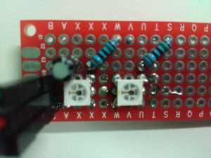
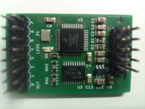
RGB leds that can be daisy chained, and are used in for example LED strips. The FadeCandy is a controller that is connected to a computer over an USB interface, and up to 8 chains of WS2812 leds.

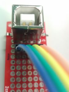
The customised part of this board is there is a pin header in stead of a mini/micro USB connector. As for that, it’s not simply plug in in a cable, thus I made a simple breakout board to connect a USB cable. I had some USB B female PCB connectors laying around, so I used one of those to connect the FadyCandy to USB.

I made soldered some of the leds to a prototyping pcb, and fried two of them in the process. At first, I didn’t read the datasheet correctly (or rather, I was too quick). The leds I got are WS2812. This is a variant with 6 pins. The WS2812B got 4 pins. The datasteet mentioned VCC and VDD as ‘Power supply control circuit’ and ‘Power supply LED’ so I connected them to the power rail. That turned out to be a mistake. The VCC should have been connected through a 150Ω resistor, so I blew up the first led. A bright flash and it was dead. Note to self: look at the reference connection diagram first. The second led probably died because I’ve overheated it during soldering. It was a little bit off-centered and I tried to correct for that. In the process I think I might have heated it too long. Nevertheless, I created a test PCB with two functional leds. Time to write some software to control those leds.

The FadeCandy controller comes with a server to control the leds. This server implements the OPC protocol. A simple protocol to control leds, which consists of a header followed by a series of RGB values. On the FadeCandy github there are some examples. However these have an abstraction layer, where one configures how the leds are positioned. This allows one to configure a 2D array of leds, and has functions to draw in this 2D array. This is way too complicated for a 2-led setup. Therefore I wrote my own implementation of the OPC protocol, that just writes some RGB values to the server.

#include <stdio.h>
#include <stdlib.h>
#include <string.h>
#include <errno.h>
#include <unistd.h>
#include <sys/socket.h>       
#include <sys/types.h>      
#include <netinet/in.h>     
#include <arpa/inet.h>    
#include <netdb.h>
#include <dlfcn.h>

int main(int argc, char* argv[]){
  int Socket;
  struct sockaddr_in saServer4;
  memset(&saServer4,0,sizeof(saServer4));

  saServer4.sin_family=AF_INET;
  saServer4.sin_port=htons(7890);
  saServer4.sin_addr.s_addr = inet_addr("127.0.0.1");

  Socket = socket(AF_INET, SOCK_STREAM, IPPROTO_IP);
  if (Socket) {
    if (connect(Socket, (struct sockaddr *)&saServer4, sizeof(saServer4))) {
      printf("Connection failed!\n");
    } else {
      printf("Connected\n");    
      uint8_t data[10];
      data[0] = 1; // channel 1
      data[1] = 0; // command 0, send RGB data

      data[2] = 0; // data size high byte
      data[3] = 6; // data size low byte

      data[4] = 255; //R
      data[5] = 0;   //G
      data[6] = 0;   //B

      data[7] = 0;   //R
      data[8] = 0;   //G
      data[9] = 255; //B
      
      send (Socket,data,sizeof(data),0);
    }
  } else printf("Socket error!\n");
}

Running this code in combination with the following config file on the FadeCandy server: (overriding the defaults, I will discuss this in a later post)

{
    "listen": [null, 7890],
    "verbose": true,
    "devices": [
        {
        "type": "fadecandy",
         "map": [
                [ 1, 0, 0, 2 ] 
            ]
        }
    ]
}

 
This allows me to control the leds. But just 2 leds is no fun, so I ordered some led strips. I will discuss those leds strips in a later post. Thanks for reading and stay tuned for the next post ;)