
So, I’ve decided to create my own controller for WS2812-compatible (SK6812, PD9823) leds. These leds are referred to as “clockless”, as they only have a data line and no clock line. 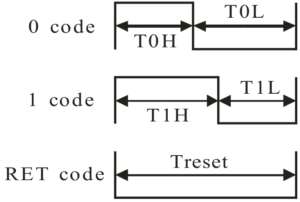 The data is transmitted in a serial protocol, which encodes a zero as a short high, long low, and a one as long high, short low. A short high pulse should be less then 440 ns, and a long high pulse should be at least 625 ns, to cover most of the variants. Using this protocol, the data is transmitted as RGB colour data, 8 bit per pixel, thus 24 bits per LED. The order is rather GRB, for SMD leds as found on LED strips, but RGB for trough hole leds (such as PD9823). The data is transmitted Most Significant Bit First. Each led on a led strip reads 24 bits and applies that colour, and forwards the remaining bits to the next led in the chain.
Looking at that protocol, I imagined it could be implemented using a PWM generator, continuously updating the PWM period. I’ve decided to implement this on an ST microcontroller, the STM32F102C8T6. I had one of these laying around. I’ve ordered such a microcontroller on eBay, over a year ago, and never gotten into doing something with it, until now. I will write another post about microcontrollers soon, but now, I am writing about my experiences controlling the ws2812-style leds. This will include some implementation details specific to the STM32F103 microcontroller.
The STM32F103 microcontroller has timer units which include a PWM mode. You set a period time, and a compare time less then the period time. This will generate a PWM signal with said period and compare time. My first naive implementation was to set the next period time in the interrupt handler when the compare time expired. My first attempt is based on the examples provided with the STM32Cube SDK. It uses the HAL provided by ST. Obviously, the first attempt didn’t work. It never does. (I wrote this months ago… there might be some details off)
void pwm_init() {

  TimHandle.Instance = TIM2;

  TimHandle.Init.Prescaler         = 9;
  TimHandle.Init.Period            = 10;
  TimHandle.Init.ClockDivision     = 0;
  TimHandle.Init.CounterMode       = TIM_COUNTERMODE_UP;
  TimHandle.Init.RepetitionCounter = 0;

  if (HAL_TIM_PWM_Init(&TimHandle) != HAL_OK) {
  /* Initialization Error */
  Error_Handler();
  }

  /*##-2- Configure the PWM channels #########################################*/
  /* Common configuration for all channels */
  sConfig.OCMode       = TIM_OCMODE_PWM1;
  sConfig.OCPolarity   = TIM_OCPOLARITY_HIGH;
  sConfig.OCFastMode   = TIM_OCFAST_DISABLE;
  sConfig.OCNPolarity  = TIM_OCNPOLARITY_HIGH;
  sConfig.OCNIdleState = TIM_OCNIDLESTATE_RESET;
  sConfig.OCIdleState  = TIM_OCIDLESTATE_RESET;

  /* Set the pulse value for channel 1 */
  sConfig.Pulse = 8;
  if (HAL_TIM_PWM_ConfigChannel(&TimHandle, &sConfig, TIM_CHANNEL_1) != HAL_OK) {
  /* Configuration Error */
  Error_Handler();
  }

  // Clear Pending IRQ and Enable IRQ.
  NVIC_ClearPendingIRQ(TIM2_IRQn);
  NVIC_EnableIRQ(TIM2_IRQn);
  }

//------------------------------------------------------------------------------

void HAL_TIM_PWM_PulseFinishedCallback(TIM_HandleTypeDef *htim) {
	uint32_t mask = 1 << bitcount++;
	if (pixelcount < 2) {
		// Set output
		sConfig.Pulse = (mask & data[pixelcount]) ? 8 : 3;

	} else {
		// reset
		sConfig.Pulse = 0;
	}

	if (HAL_TIM_PWM_ConfigChannel(&TimHandle, &sConfig, TIM_CHANNEL_1) != HAL_OK) {
	    // Configuration Error
	    Error_Handler();
	}

	if (bitcount == 24) {
		bitcount = 0;
		pixelcount++;

	}
	if (pixelcount == 4) pixelcount = 0;
	}
}

//------------------------------------------------------------------------------

void HAL_TIM_PeriodElapsedCallback(TIM_HandleTypeDef *htim) {
	//trace_printf("Callback on channel %u\n", htim->Channel);
}
In this example, I store each pixel, or led value, in a 32 bit integer. I run through a bitmask, going from bit 0 to bit 23, as I have a 24 bit colour value in there, and I set the pulse width of the next pulse accordingly to 3 or 8. Seems quite straight forwards. But it didn’t work. Well… when it doesn’t work… how to find what’s going wrong?
To me, the first approach would be to get rid of the HAL, and controlling the registers myself. I mean… so see what’s going wrong, you have to see what is going on. So, that would give me the following code: (again, I wrote this months ago… there might be some details off)
void TIM2_IRQHandler (void) {
	if (TIM2->SR &0b01) {
		TIM2->SR &=~0b01;

	  uint32_t mask = 1 << bitcount++;
	  if (pixelcount < 2) {
		  TIM2->CCR1 = (mask & data[pixelcount]) ? 8 : 3;
	  } else {
		  TIM2->CCR1 = 0;
	  }

	  if (bitcount == 24) {
		  bitcount = 0;
		  pixelcount++;
	  }
	  if (pixelcount == 4) pixelcount = 0;

	}
}

//------------------------------------------------------------------------------
void pins_init() {
  GPIO_InitTypeDef   GPIO_InitStruct;

  // Enable Timer 2 Clock
  __HAL_RCC_TIM2_CLK_ENABLE();

  // Enable GPIO Port A Clock
  __HAL_RCC_GPIOA_CLK_ENABLE();

  // Common configuration for all channels
  GPIO_InitStruct.Mode = GPIO_MODE_AF_PP;
  GPIO_InitStruct.Pull = GPIO_PULLUP;
  GPIO_InitStruct.Speed = GPIO_SPEED_FREQ_HIGH;

  // Apply pin configuration to PA0
  GPIO_InitStruct.Pin = GPIO_PIN_0;
  HAL_GPIO_Init(GPIOA, &GPIO_InitStruct);

  // Apply pin configuration to PA1
  GPIO_InitStruct.Pin = GPIO_PIN_1;
  HAL_GPIO_Init(GPIOA, &GPIO_InitStruct);

  // Apply pin configuration to PA2
  GPIO_InitStruct.Pin = GPIO_PIN_2;
  HAL_GPIO_Init(GPIOA, &GPIO_InitStruct);

  // Apply pin configuration to PA3
  GPIO_InitStruct.Pin = GPIO_PIN_3;
  HAL_GPIO_Init(GPIOA, &GPIO_InitStruct);
}


void pwm_init() {
	pins_init();
	NVIC->ISER[0] |= 0x10000000;
	RCC->APB1ENR |= 1;
	TIM2->ARR = 10 ; // Reload Value
	TIM2->PSC =  9 ; // Prescaler
	TIM2->CCMR1 = ( TIM2->CCMR1  & ~(0b11110000) ) | (0b1101 << 3);  // Set Channel 1 to PWM mode 1 and enabling reload
	TIM2->CR1 |= 1 << 7; // auto reload enable
	TIM2->EGR |= 1; // Set UG bit
	TIM2->CR1 &= ~(0b1110000); // Edge aglined, upcounting
	TIM2->CR1 |= 0b100; // Event source, only over/underflow
	TIM2->DIER = 0x0001; // interrupt enable
	TIM2->CCER |= 0b1;  // output enable and polarity
	TIM2->CCR1 = 0; // output val
	TIM2->CR1 |= 0x0001; // enable
  NVIC_ClearPendingIRQ(TIM2_IRQn);
  NVIC_EnableIRQ(TIM2_IRQn);
}
Basically, doing the same thing, but without the HAL. Here see directly what is going on with the registers we set. But of course this didn’t work either. Blaming the HAL is too easy. But let’s have a look at what is going wrong. (This is stuff I wrote months ago… at least at this point, I have some material describing what went wrong). Every bit I output is outputted twice.
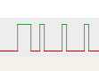 Expected outbut |
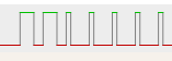 Actual output |
Basically, the problem here is, the time I spend in the interrupt handler is too much. The time it takes to update the pulse width is longer then the time left in the period, this the value is not ready yet when the next period starts. Thus, the current value is outputted twice.
So, this means, I cannot calculate the next value on the fly. I need to have the values ready when I start outputting them. The timer hardware supports DMA transfers, so I could point it to a block of memory containing the values I need to output. However, doing so would need quite some more RAM. I will discuss details of this approach in a next post, thanks for reading.