
A while ago, I got a customised FadeCandy board and some WS2812 leds from a friend. A FadeCandy is a controller for WS2812 leds (and variants). WS2812 leds are individually addressable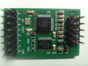 RGB leds that can be daisy chained, and are used in for example LED strips. The FadeCandy is a controller that is connected to a computer over an USB interface, and up to 8 chains of WS2812 leds.
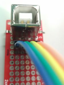 The customised part of this board is there is a pin header in stead of a mini/micro USB connector. As for that, it’s not simply plug in in a cable, thus I made a simple breakout board to connect a USB cable. I had some USB B female PCB connectors laying around, so I used one of those to connect the FadyCandy to USB.
I made soldered some of the leds to a prototyping pcb, and fried two of them in the process. At first, I didn’t read the datasheet correctly (or rather, I was too quick). The leds I got are WS2812. This is a variant with 6 pins. The WS2812B got 4 pins. 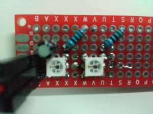 The datasteet mentioned VCC and VDD as ‘Power supply control circuit’ and ‘Power supply LED’ so I connected them to the power rail. That turned out to be a mistake. The VCC should have been connected through a 150Ω resistor, so I blew up the first led. A bright flash and it was dead. Note to self: look at the reference connection diagram first. The second led probably died because I’ve overheated it during soldering. It was a little bit off-centered and I tried to correct for that. In the process I think I might have heated it too long. Nevertheless, I created a test PCB with two functional leds. Time to write some software to control those leds.
The FadeCandy controller comes with a server to control the leds. This server implements the OPC protocol. A simple protocol to control leds, which consists of a header followed by a series of RGB values. On the FadeCandy github there are some examples. However these have an abstraction layer, where one configures how the leds are positioned. This allows one to configure a 2D array of leds, and has functions to draw in this 2D array. This is way too complicated for a 2-led setup. Therefore I wrote my own implementation of the OPC protocol, that just writes some RGB values to the server.
#include <stdio.h>
#include <stdlib.h>
#include <string.h>
#include <errno.h>
#include <unistd.h>
#include <sys/socket.h>
#include <sys/types.h>
#include <netinet/in.h>
#include <arpa/inet.h>
#include <netdb.h>
#include <dlfcn.h>

int main(int argc, char* argv[]){
  int Socket;
  struct sockaddr_in saServer4;
  memset(&saServer4,0,sizeof(saServer4));

  saServer4.sin_family=AF_INET;
  saServer4.sin_port=htons(7890);
  saServer4.sin_addr.s_addr = inet_addr("127.0.0.1");

  Socket = socket(AF_INET, SOCK_STREAM, IPPROTO_IP);
  if (Socket) {
    if (connect(Socket, (struct sockaddr *)&saServer4, sizeof(saServer4))) {
      printf("Connection failed!\n");
    } else {
      printf("Connected\n");
      uint8_t data[10];
      data[0] = 1; // channel 1
      data[1] = 0; // command 0, send RGB data

      data[2] = 0; // data size high byte
      data[3] = 6; // data size low byte

      data[4] = 255; //R
      data[5] = 0;   //G
      data[6] = 0;   //B

      data[7] = 0;   //R
      data[8] = 0;   //G
      data[9] = 255; //B

      send (Socket,data,sizeof(data),0);
    }
  } else printf("Socket error!\n");
}
Running this code in combination with the following config file on the FadeCandy server: (overriding the defaults, I will discuss this in a later post)
{
    "listen": [null, 7890],
    "verbose": true,
    "devices": [
        {
        "type": "fadecandy",
         "map": [
                [ 1, 0, 0, 2 ]
            ]
        }
    ]
}
This allows me to control the leds. But just 2 leds is no fun, so I ordered some led strips. I will discuss those leds strips in a later post. Thanks for reading and stay tuned for the next post ;)
1 Trackback or Pingback for this entry:
[…] few years ago I discussed WS2812-compatible (ws2812, sk6812, pd9823, …) LEDs https://andre.blaatschaap.be/2017/03/led-there-be-light-part-1/ https://andre.blaatschaap.be/2017/07/led-there-be-light-part-2/ […]